Introduction
A Onewheel is a self-balancing electric board with a single wheel in the middle. The board I ride is a Onewheel+ XR. It is an older model, but it is definitely not stock. It already had been upgraded with the FloatWheel XRV kit, which replaces the stock electronics with a VESC-based controller. That kit gave me a lot more torque and higher top speed. But once the XRV was running, the stock battery became the bottleneck. So I decided to build a custom pack with more power and better range.
A Word to the Wise
Before getting into the details, I want to say this configuration is not ideal. I was working with parts I already had on hand, and I had fun solving the quirks that popped up. But I would not recommend building a 16s2p pack. If I had to do this build over again, I would just buy the Torque Box, build a 15s2p battery, and reuse the XRV BMS.
Design Constraints
A few physical and electrical limits dictated the battery design:
- Enclosure space: The stock XR battery box is tiny. You cannot fit a significant cell upgrade inside it. I swapped the stock box for a Torque Box from The Float Life, which I found on Facebook Marketplace. The Torque Box has enough clearance for up to 38 21700 cells.
- Controller voltage: The XRV controller supports up to a 20s pack (84V fully charged).
- Wiring harness: The wiring harness running between the battery box and controller box limits current flow and dictates how charging has to work.
Cells and Configuration
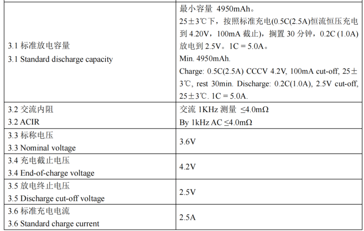
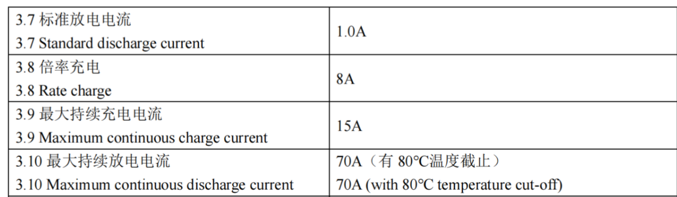
I wanted 21700 cells. I chose the EVE RS50 because of its 4.95Ah capacity, 70A continuous discharge rating, and solid reputation in the PEV community. In hindsight, 70A continuous is complete overkill for a board like this. A cell rated around 30A would of had plenty of headroom.
I settled on a 16s2p layout (32 cells total). That configuration yields 9.9Ah at 57.6V nominal (67.2V max), which is more than double the capacity of the original stock XR pack (15s2p of 18650s, 4.2Ah total). It stays well inside the controller voltage ceiling and fits cleanly inside the box.
I also considered 18s2p and 30s1p layouts. An 18s2p pack would not leave enough room for 3D-printed cell spacers inside the box. A 30s1p pack would run at 126V, which blows way past the controller limit.
As I stated in the intro, going with 15s2p would have meant slightly less capacity, but it would have kept the stock voltage and let me reuse the XRV BMS without rewiring the main cable harness.
BMS Selection
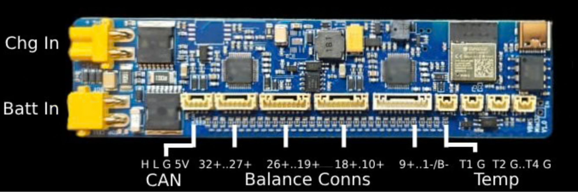
I picked up a Fungineers vfBMS from the same seller who sold me the Torque Box. It is a charge-only BMS that balances up to 20 series groups.
Onewheels rely on charge-only BMS units. You need uninterrupted power to the motor so the board can keep you upright. If a discharge BMS cuts power while you are moving, you get thrown off at speed.
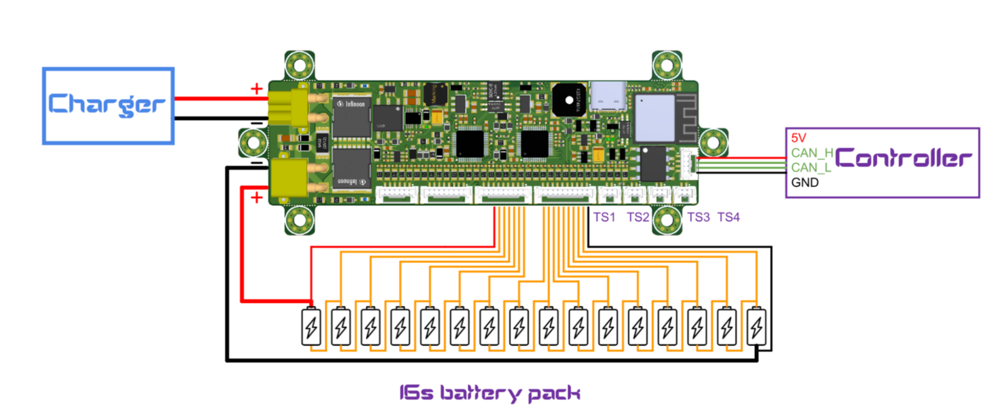
Because 16s2p is such an oddball configuration for this board, nobody had documented using it with the vfBMS. I messaged Fungineers support to ask about the 16s balance lead pinout, but they did not have a diagram for it. Fortunately, the JetFleet BMS32 uses almost the exact same board architecture. JetFleet had a published 16s balance lead diagram, and it worked right away.
The vfBMS has two balancing ICs on board. Each chip handles between 3 and 16 cells. Since my pack is exactly 16s, I only needed to wire up the first IC.
The Fusing Debate
There is an ongoing argument in the PEV and DIY Onewheel communities about whether to fuse the main discharge line between the battery and the controller.
The two sides see risk differently:
- Pro-fuse: You want to protect the controller and wiring from melting down during a dead short.
- Anti-fuse: You would rather risk blowing up the controller than risk an unexpected motor shutoff mid-ride.
The obvious objection here is that putting a fuse on the discharge line of a self-balancing board invites a nosedive. If that fuse blows while you are leaning forward at 20 mph, the board cuts out and you hit the pavement hard. That objection is fair, and it is why many builders refuse to fuse the discharge leads. But a direct short without a fuse drops the board too, and then you have a thermal runaway fire between your feet.
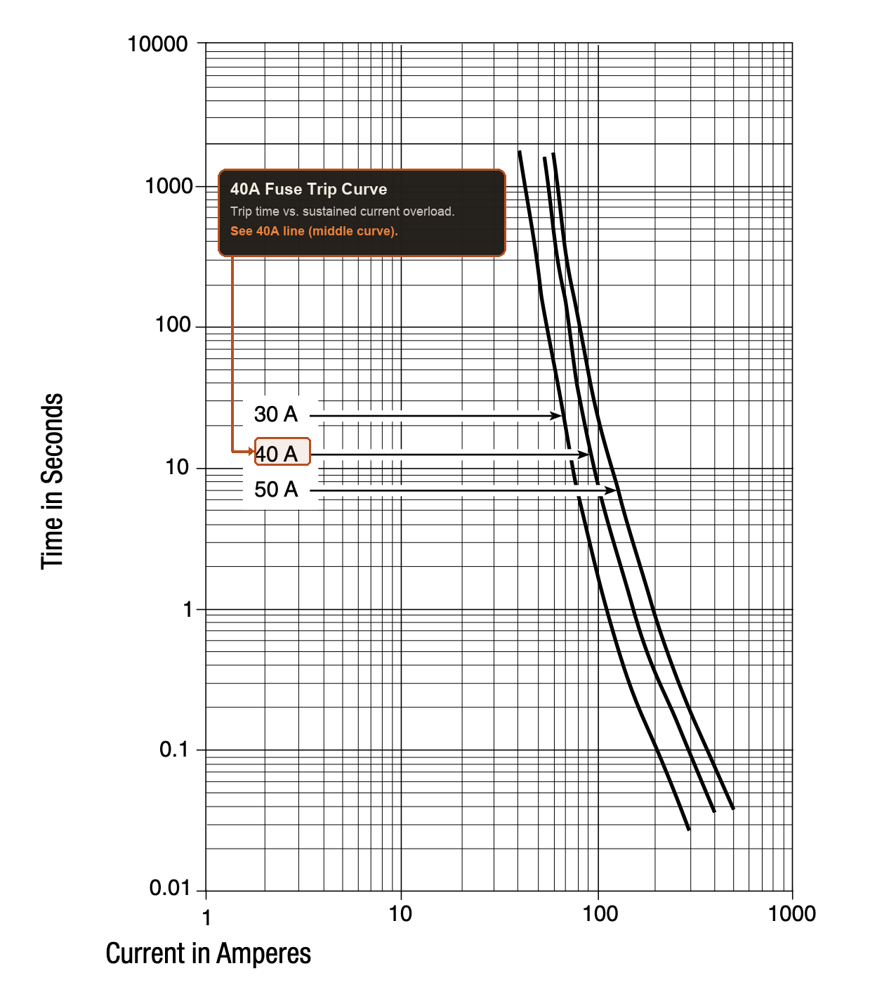
I decided to fuse both discharge and charge lines. For discharge, I used a 40A slow-blow fuse rated for 80VDC (Schurter 40A fuse on DigiKey). The pack operates at 67.2V max, well under the 80V rating.
A 40A rating does not mean the fuse trips the instant current touches 40A. Because it is a slow-blow fuse, current has to stay above that threshold for a specific duration to blow the element. That curve handles short acceleration spikes without cutting power, but it will still pop during a sustained short.
For the charge port, I installed a 10A fast-blow fuse rated for 125V (Littelfuse 10A on DigiKey). I charge at 3A, so 10A gives plenty of headroom while protecting against reverse polarity and charger faults.
You can read through the community discussions on fusing over at pev.dev and esk8.news.
Modifying the Wiring Harness
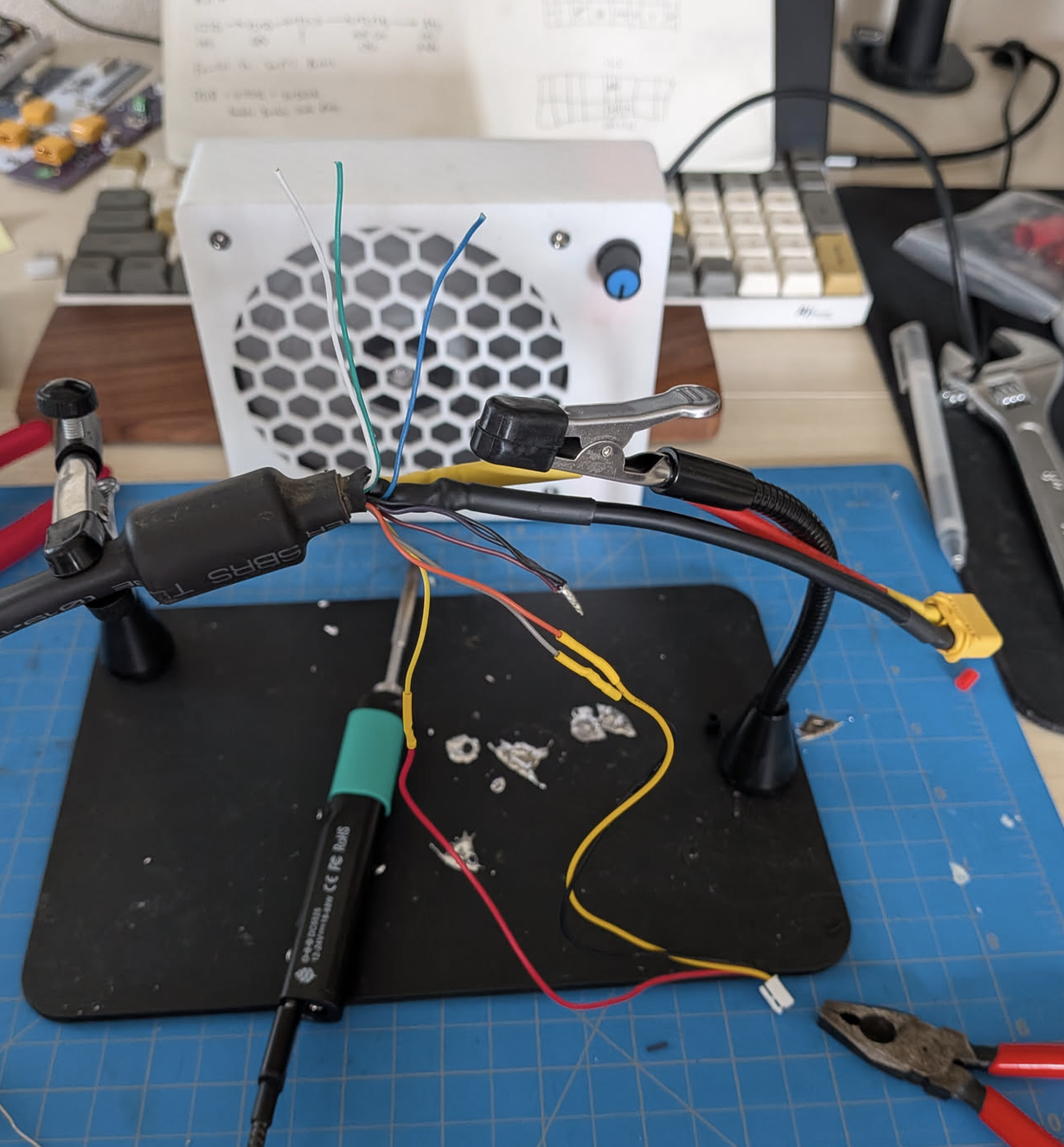
The trickiest packaging issue came down to the wiring harness connecting the battery box and controller box.
Keep in mind, this board was not running stock electronics. It had the XRV kit installed. On a factory board, the BMS handles both charging and discharge through a single pair of main power wires. The vfBMS I chose only handles charging, so it needs separate lines for charge-in and battery-in. The wiring harness was never designed for dedicated charge leads.
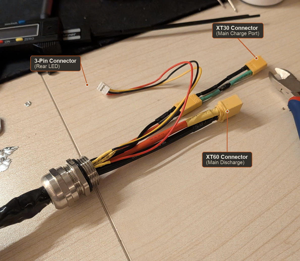
I solved this by repurposing six unused small-gauge wires in the harness: five original BMS communication wires, plus an extra rear light lead. I bundled them into two groups of three ~20 AWG wires for charge positive and charge negative. Three 20 AWG lines in parallel give plenty of copper for 3A charging.
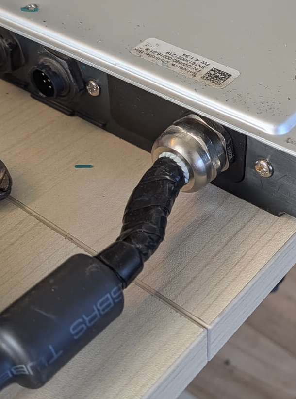
At the controller box, the XRV kit connects to the harness using its own 16-pin Molex connector PCB. That PCB locked down the pinout and stood in the way of running separate high-current and charge leads. So I pulled the XRV Molex connector and printed an adapter for a 20mm cable gland (Printables XR Molex Converter). That gave me direct pass-through access into the controller box without being constrained by the XRV PCB.
I soldered all the repurposed lines for charging (terminated with an XT30), the 3-pin rear LED connector, and the main discharge leads (XT60), then wrapped the exposed section of the harness with silicone tape for water and abrasion resistance.
Construction
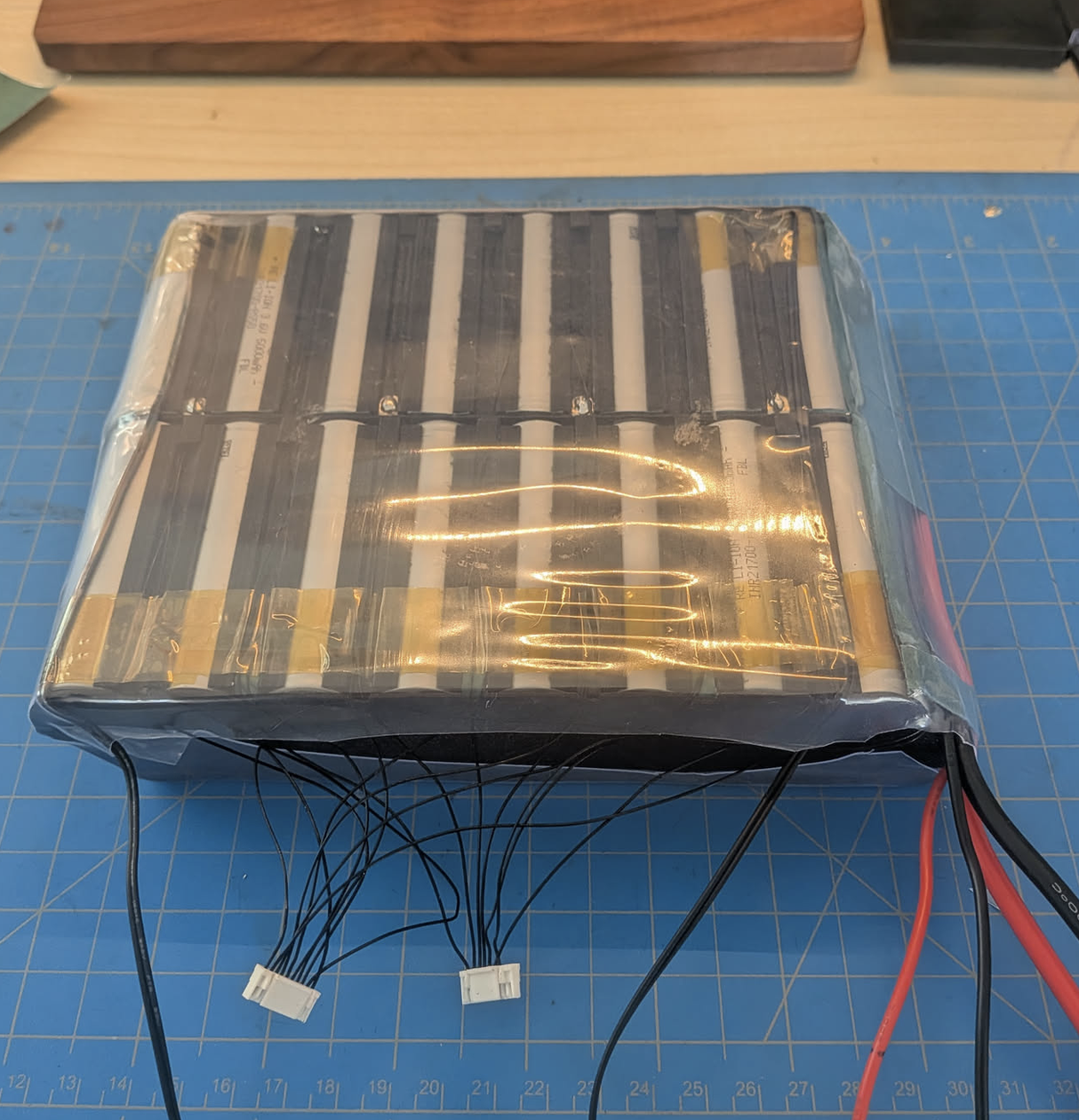
I designed the cell layout and interlocking spacers in OnShape. Once the dimensions checked out, I printed the spacers in PETG and spot-welded each half of the pack.
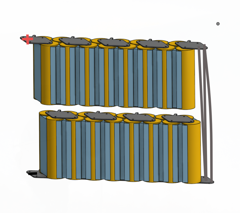
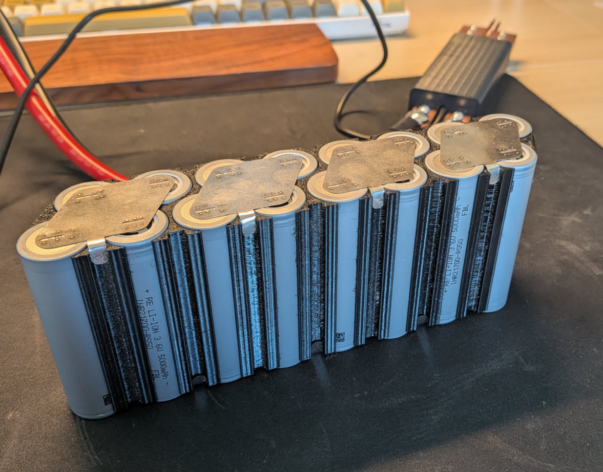
I soldered the BMS balance leads to the first half of the pack before joining the two halves together with side nickel strips. A 3D-printed PETG center spacer sits between the halves to stop any chance of cells touching.
I added adhesive fish paper along both faces of the pack to isolate the nickel strips and main conductors. I also placed two NTC temperature probes in contact with the cells at opposite ends of the pack. Finally, I sealed the whole assembly in PVC heat shrink.
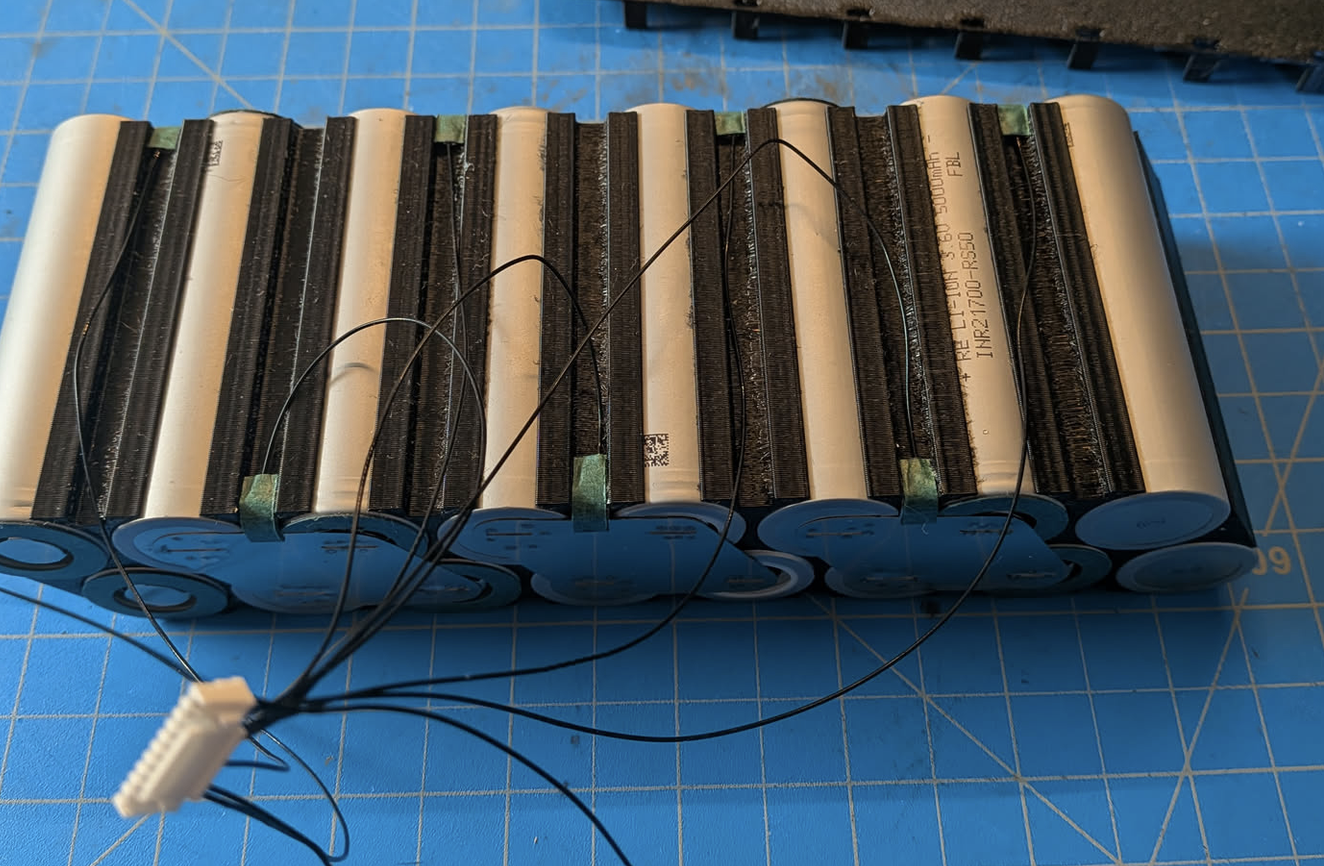
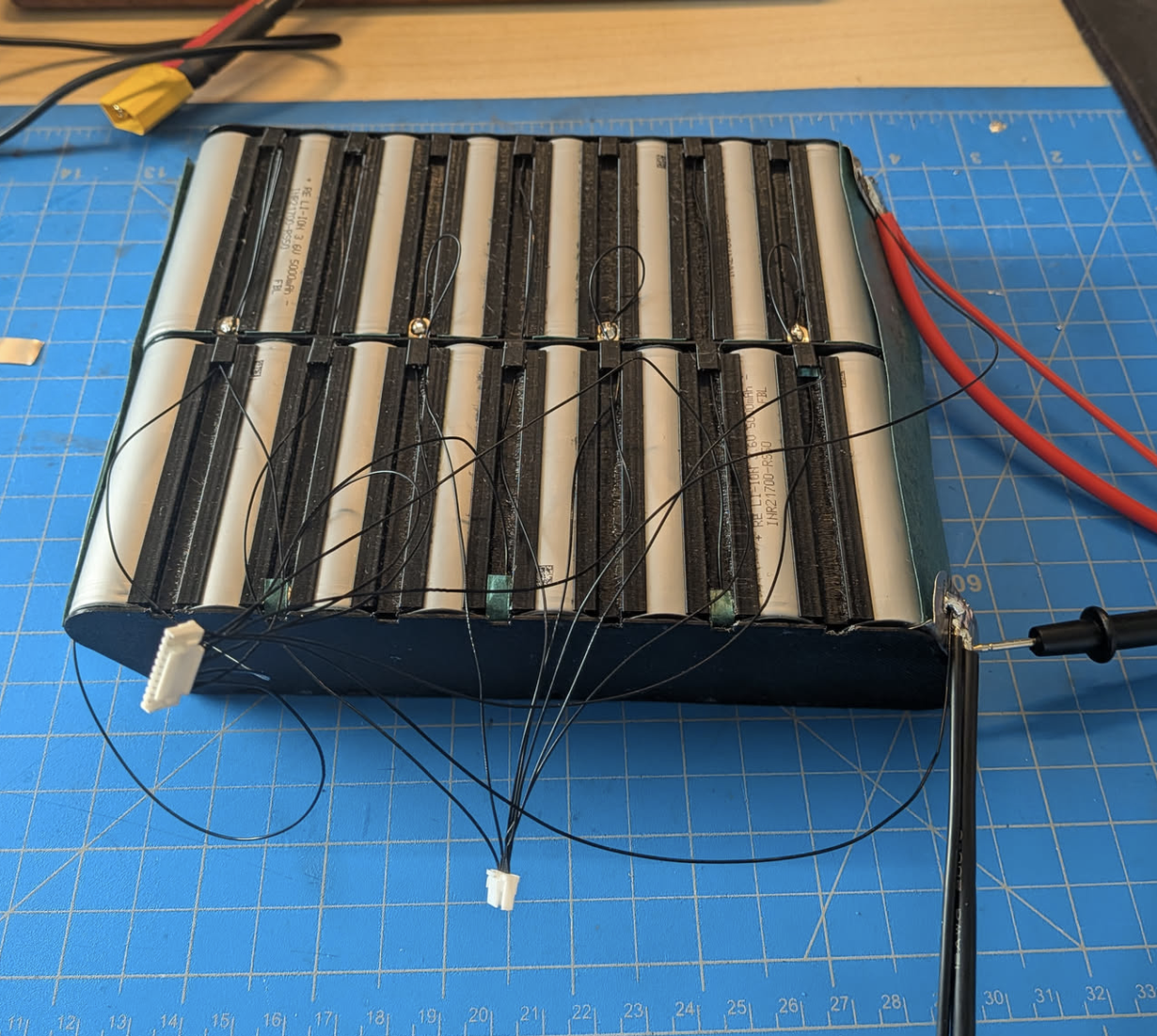
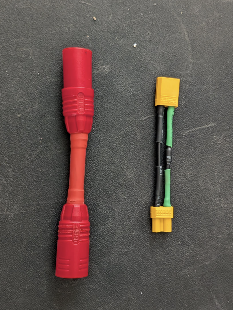
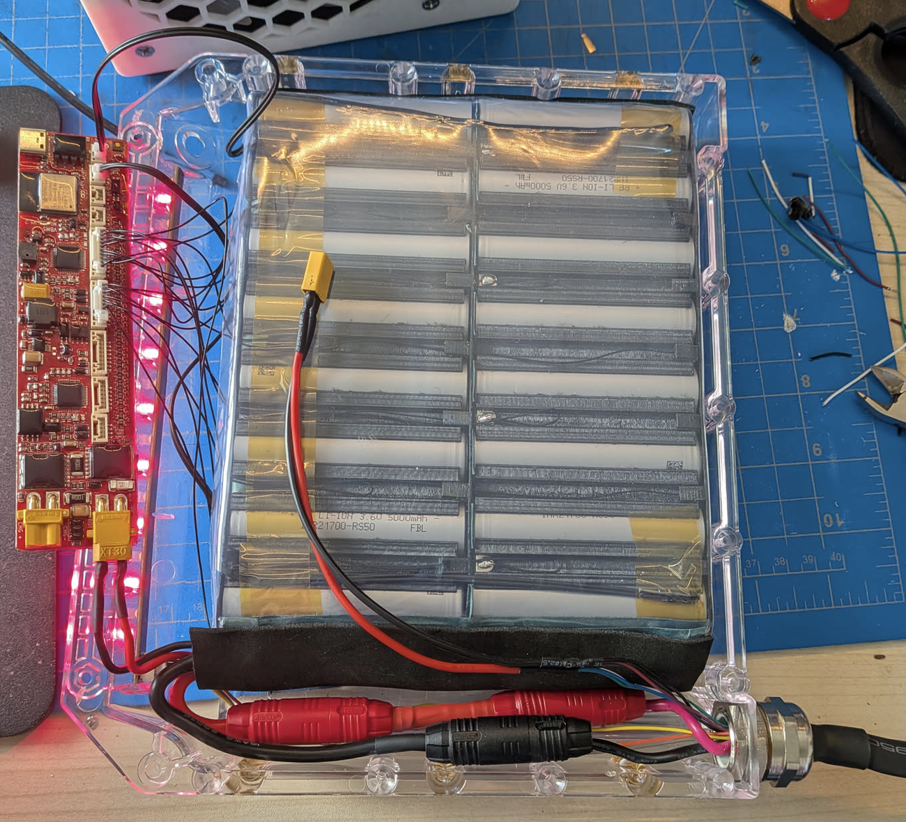
For the main power connections, I used an AS150 anti-spark connector on the battery positive lead and the inline fuse holder. The anti-spark resistor prevents arcing when plugging the battery into the controller. On the controller side, I used an XT60 for convenience, though using AS150 there too would have given a better current rating. The charge port connects through an XT30.
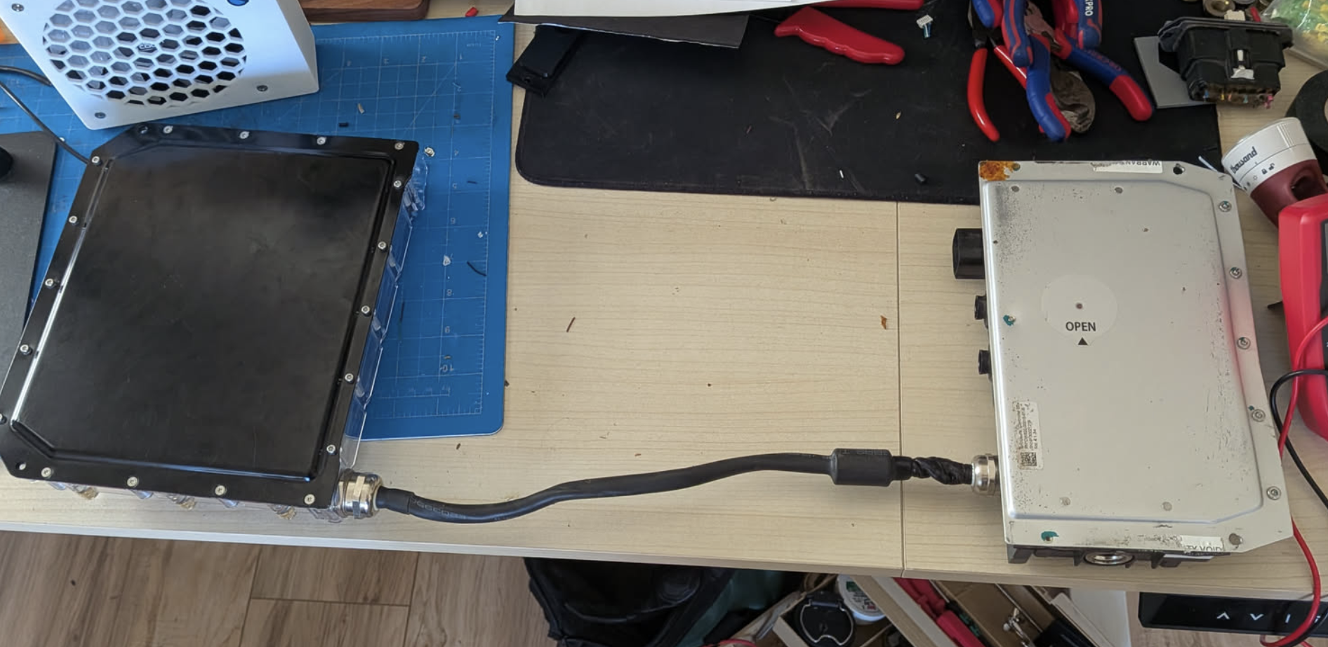
Before screwing the lid down, I connected everything on the bench to confirm the vfBMS and controller powered up and functioned properly.
Results
After bolting the Torque Box shut, I geared up with a helmet and wrist guards for a test ride. I was cautious on the first loop, but the board ran smoothly with zero cutouts or thermal warnings.
I have been riding this pack for a couple of weeks now. On a recent 10-mile ride, the battery only dropped from 100% down to 75%. That works out to roughly 40 miles of total range on a single charge. The board gained some weight over stock, but it is still easy to carry. Even though the 16s wiring took more effort than a standard 15s build, the extra torque and range made the work worthwhile.